Form Tolerances: straightness, flatness, circularity and cylindricity
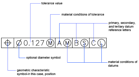
http://docs.autodesk.com/ACD/2010/ENU/AutoCAD%202010%20User%20Documentation/index.html?url=WS1a9193826455f5ffa23ce210c4a30acaf-611d.htm,topicNumber=d0e134828
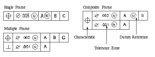
http://www.viewmold.com/ug_html_files/ugopen_doc/uf_gdt/uf_gdt_ref1.html
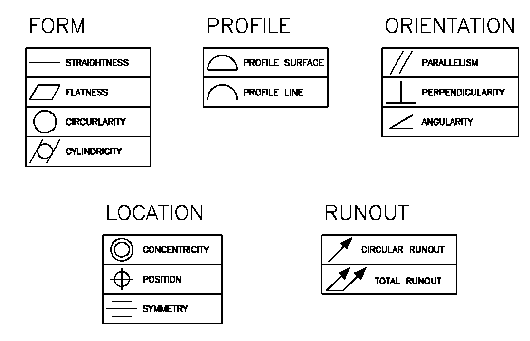
http://www.manufacturinget.org/home/4472-computer-aided-design/geometric-dimensioning-and-tolerancing/
Symbols used in a "feature control frame" to specify a feature's description, tolerance, modifier and datum references
| Symbol |
Modifier |
Notes |
|
Free state |
Applies only when part is otherwise restrained |
|
Least material condition (LMC) |
Useful to maintain minimum wall thickness |
|
Maximum material condition (MMC) |
Provides bonus tolerance only for a feature of size |
|
Projected tolerance zone |
Useful on threaded holes for long studs |
|
Regardless of feature size (RFS) |
Not part of the 1994 version. See para. A5, bullet 3. Also para. D3. Also, Figure 3-8. |
|
Tangent plane |
Useful for interfaces where form is not required |
|
Unilateral |
Appears in the 2009 version of the standard, and refers to unequal profile distribution. |
https://en.wikipedia.org/wiki/Geometric_dimensioning_and_tolerancing
Datums and datum references[edit]
Concentricity
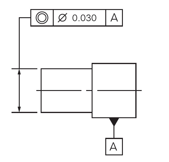
http://www.gdandtbasics.com/concentricity/
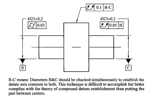
http://www.geotolmeadows.com/newsletters/2012/nov2012.htm


